Distribution Switchboards
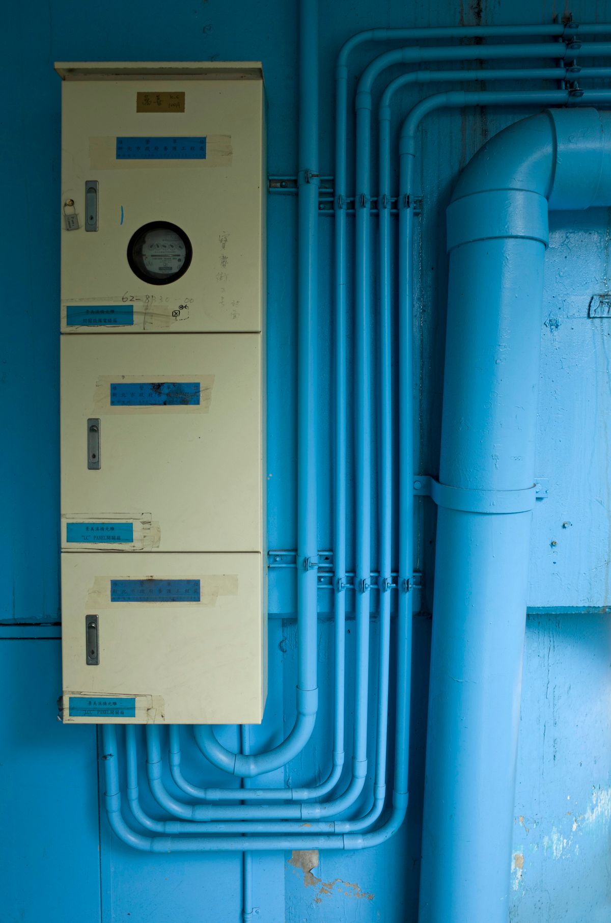
Multi-feeder distribution switchboards for the downstream distribution of power across industrial facilities, commercial towers, and large campuses. Designed for selective coordination and easy expansion.
Distribute Power Across the Entire Facility
Distribution switchboards serve as the central node for breaking a large feeder into sub-feeders serving MCCs, panelboards, and individual equipment. Our designs are laid out for accessibility, selective coordination, and future expansion — with spare breaker spaces and spare bus capacity built in.
- Multiple feeder MCCBs and ACBs in a single lineup
- Full-capacity copper bus with spare space for expansion
- Selective coordination between main and all feeders
- Panelboard sub-feed lugs and section breaks available
- MCC interface (large-frame MCCBs or starters)
- Branch circuit metering and sub-metering options
What's Included
- Multi-feeder MCCB and ACB sections (up to 42+ poles)
- Full-capacity copper bus — spare capacity for expansion
- Selective coordination report available on request
- Panelboard sub-feed lugs (bolt-on and plug-in style)
- Top and bottom cable entry; conduit fill calculations available
- Section breakers for load grouping and isolation
- Tie lugs for future paralleling
- Ground bus run-length and equipment bonding points
- Labeling and directory per NEC/CEC requirements
- +Branch circuit metering module (per-feeder kWh)
- +Power quality analyser on main bus
- +SCADA/BMS integration via Modbus or BACnet
- +Bus plug (plug-in bus duct) takeoff sections
- +Fusible disconnect switches for motor branch circuits
- +Harmonic-rated copper bus for VFD-heavy loads
- +Spare breaker stabs populated for future use
- +Witnessed factory acceptance testing (FAT)
Full Specifications
| Parameter | Value |
|---|---|
| Voltage | 120/208 V, 277/480 V, 347/600 V (3Ø, 4W) |
| Main Bus Rating | 800 A–3200 A (continuous) |
| AIC Rating | Up to 65 kA symmetrical |
| Feeder Devices | MCCB (15–1200 A), ACB (800–4000 A) |
| Bus Material | Copper, silver-plated contacts; optional aluminum |
| Enclosure | NEMA 1; NEMA 3R available for service entrances |
| Sub-Feed Options | Panelboard sub-feed lugs, bus duct tap, cable |
| Finish | ANSI 61 powder coat |
| Standards | UL 891, CSA C22.2 No. 29, NEMA PB 2 |
| Lead Time | 4–8 weeks typical |
Built to Standard



Where It's Used
- Industrial plant distribution to MCCs and panelboards
- Office tower floor-by-floor electrical distribution
- Hospital and healthcare facility power distribution
- University campus multi-building distribution
- Retail mall distribution to tenant service panels
- Airport concourse and terminal power distribution
- Wastewater treatment plant electrical distribution
- Transit station and maintenance facility distribution
From design and specification through factory testing, commissioning, and ongoing maintenance — Candron delivers at every phase.
- Engineering drawings and coordination studies
- Factory acceptance testing (FAT) with full reports
- Site commissioning and protection settings
- Spare parts, training, and maintenance support
Common Questions
The bus rating must equal or exceed the sum of all connected load diversity, with the main breaker rated at or below the bus. We perform load calculations per CEC/NEC Section 220 or your single-line diagram and recommend the correct bus rating — including spare capacity for future loads.
Yes — we can deliver a time-current curve coordination study showing that feeder breakers will clear before the main, ensuring maximum service continuity. This is particularly important for facilities with VFDs, motors, or sensitive process loads.
As a rule of thumb, we recommend 20–25% spare bus capacity and at least 4–6 spare breaker positions in the initial design. Electrical loads in facilities typically grow by 10–15% within the first five years of occupancy.
Ready to Spec
Your Project?
Our engineering team responds with specs, lead times, and pricing the same day. Tell us what you need:
- Nominal voltage and bus rating required
- List of feeders: rating (A), trip type, load description
- Any sub-feed panelboard or bus duct connections
- Metering or sub-metering requirements
- Expansion requirements (spare spaces, future bus capacity)
- Installation location and AHJ
Send us your project details and we'll respond with a price, lead time, and any clarifying questions — typically within a few hours.
Request a Quote →Or call us directly